
Plastic pyrolysis plant for PP, PE and PS waste
A pyrolysis line converts mixed polyolefin waste into fuel oil, carbon black and combustible gas. The design of the reactor, the condenser train and the discharge system is set by your material — not by a fixed catalogue model.
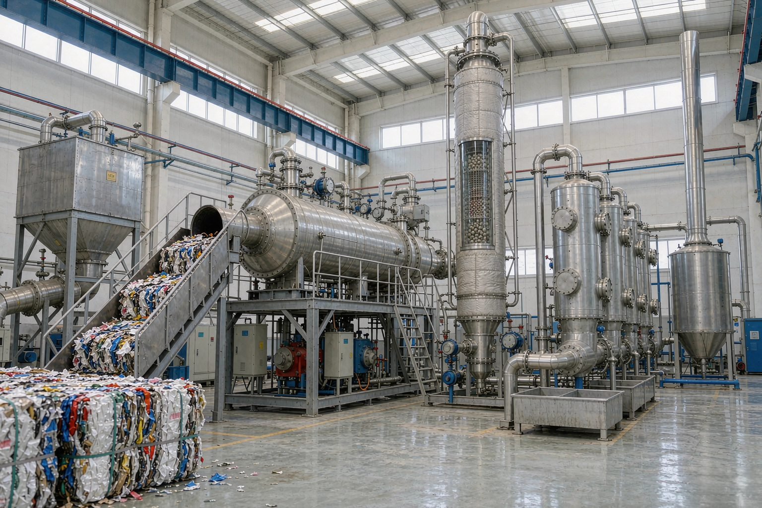
PP / PE / PS waste
Set per project
Batch only
Fuel oil, carbon black, gas
What the plant will and will not process
Pyrolysis is not a solution for every plastic stream. The two lists below are the honest boundary of the process — send a sample and we will confirm where your material sits before you commit to a line.
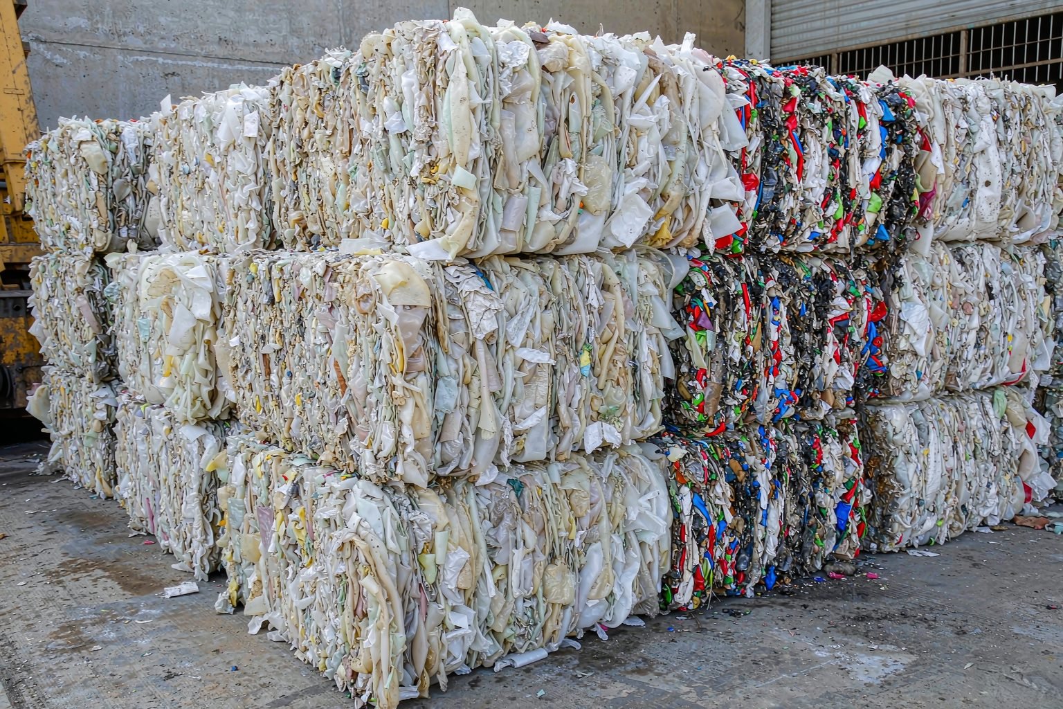
Suitable feedstock
- LDPE, HDPE and LLDPE film and rigid waste
- PP raffia, woven bags, caps and crates
- PS and EPS packaging waste
- Clean or lightly contaminated mixed polyolefins
- Plastic-rich light fraction from sorting plants
Not suitable without pre-treatment
- PET — carries oxygen into the reaction, lowers oil quality
- PVC — releases hydrogen chloride, corrodes the reactor
- Wet or high-moisture material — must be dried first
- Material with high sand, glass or metal content
- Halogenated or heavily printed film
Batch operation — the only configuration we build for plastic
Plastic is charged, heated and discharged in cycles. We do not offer semi-continuous or continuous configurations for plastic: molten plastic turns tacky and bridges in a screw or rotary feeder, and the carbon black it leaves is fine and sticky, so it will not discharge at a metered rate.
Batch
Why we do not offer semi-continuous or continuous
- Molten plastic turns tacky and bridges in a screw or rotary feeder
- Fine, sticky carbon black will not discharge at a metered rate
- Bale-to-bale quality varies — a batch lets you trim each charge
- Batch tolerates an irregular or seasonal supply of material
Optional configuration for a plastic line
The reactor, condenser train and discharge system are standard on every line. This option changes how much labour the plant needs at the feeding end.
Automatic feeding machine
Feeds the reactor mechanically instead of by hand — conveyor or screw feed into the hopper at a controlled rate. It cuts the crew needed per shift and keeps every charge consistent, which is what makes cycle times and oil quality repeatable.
From baled waste to stored oil
Six stages, each with its own control point. The condenser train and the discharge system are where a low-cost line usually differs from a workable one.
01
Charging
02
Heating
03
Vapour transfer
04
Condensation
05
Oil collection
06
Discharge
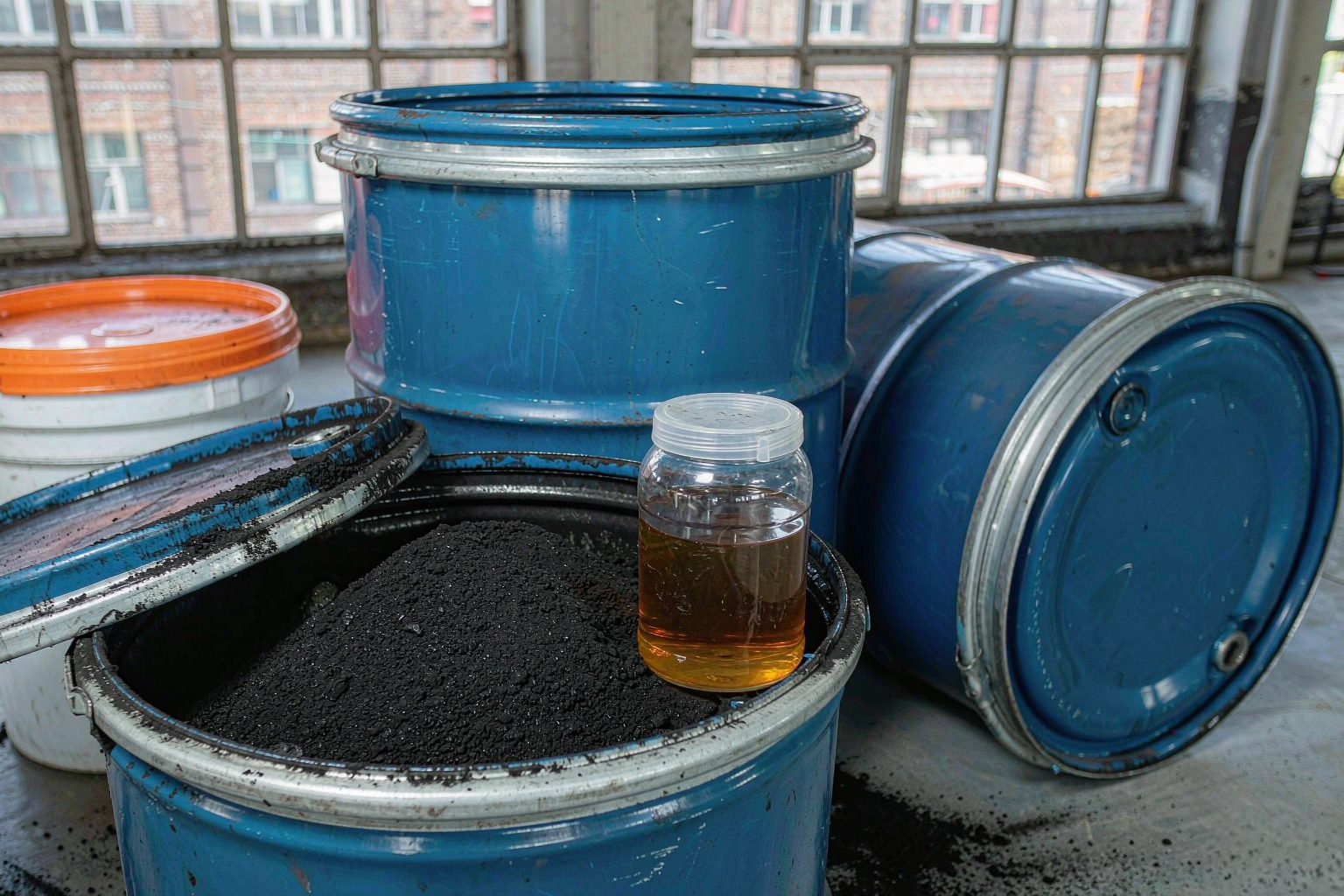
Three products leave the plant
Fuel oil
The main revenue stream. Sold as industrial fuel, or upgraded in a distillation unit into lighter fractions.
Carbon black
Discharged as a powder or granule. Sold as a filler or fuel, or briquetted for easier handling.
Combustible gas
Returned to the burner to heat the reactor, reducing the external fuel the line consumes.
Specification sheet
Values that depend on the project are marked as such rather than filled with a generic figure. The signed technical offer carries the numbers for your line.
| Reactor material | Carbon steel with refractory lining; stainless option on request |
|---|---|
| Operating pressure | Atmospheric to slight negative pressure |
| Heating method | External burner, fuel oil or gas fired |
| Cooling | Water-cooled condenser train |
| Operating mode | Batch, single reactor — no semi-continuous or continuous option |
| Daily capacity | Set per project for the batch configuration |
| Oil yield basis | Stated per project after feedstock sample assessment |
| Power supply | Specified from the site electrical conditions |
| Floor area | Layout drawing issued with the technical proposal |
| Operating staff | Stated per configuration in the proposal |
| Warranty | Per contract terms |
Send your material data
What surrounds the reactor decides how well the line runs
The reactor is the visible part. Feeding, condensation, dust removal and gas handling are what determine oil quality, downtime and whether the site can be permitted.
- Feeding conveyor or screw feeder with hopper
- Catalytic tower and dust removal stage
- Water-cooled condenser train and oil-water separator
- Oil storage tanks and transfer pump
- Carbon black screw discharge and collection
- Flue gas scrubber and induced draft fan
- Gas recovery line back to the burner
- Control cabinet with temperature and pressure interlocks
Environmental scope
- Flue gas scrubbing before stack
- Vapour recovery on the oil side
- Wastewater collection and separation
- Dust control at feeding and discharge
Permitting is a local process. We prepare the technical documentation your authority asks for; we do not issue permits or guarantee an approval.
Explore the related equipment
Four lines cover the waste-to-oil range. Open the one that matches your feedstock — each page carries the process, specification and enquiry form.
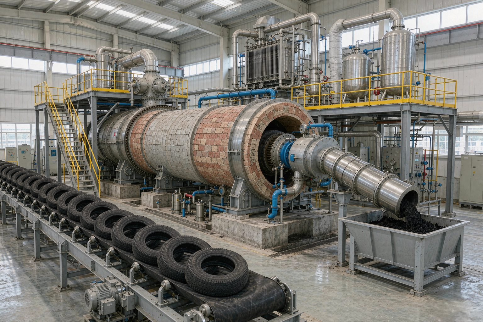
Tyre pyrolysis plant
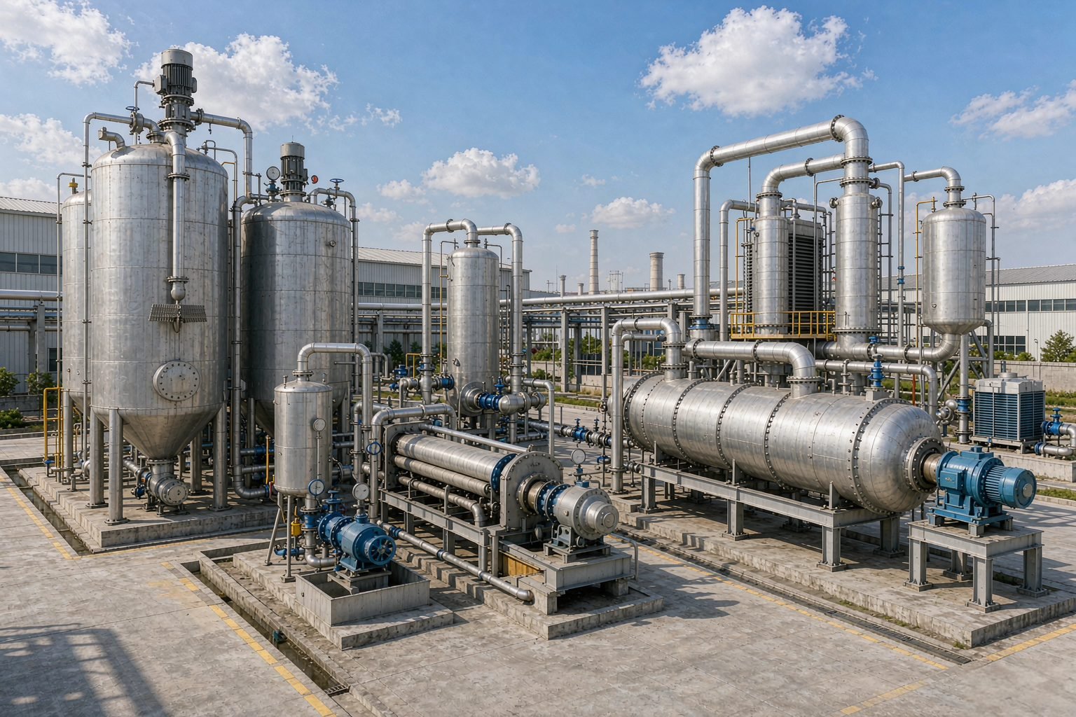
Oil sludge pyrolysis plant
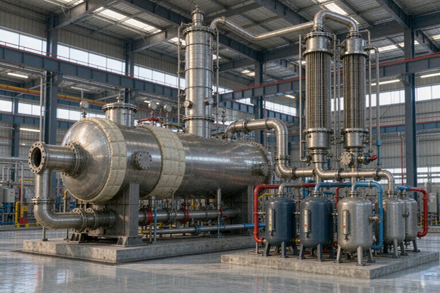
Waste oil distillation plant
A reference is only useful if it matches your feedstock
Tell us the material and the tonnage. We will send the projects that actually match — with capacity, commissioning date and the site you can contact — instead of a gallery of unrelated installations.
Before you order
It depends on the polymer mix, moisture and inert content. We state a range with the calculation basis in the proposal rather than a single marketing figure.
No. Plastic plants are batch units only. Molten plastic bridges and sticks in a metered feeder, and the fine carbon black will not discharge continuously — a continuous line would be cleaning-blocked rather than producing. Batch is the configuration that runs reliably on plastic.
Yes. The feed system, pumps, fans and controls run on electricity, so the site supply is one of the four inputs we need before quoting.
It depends on the configuration, the site preparation and the shipping route. The schedule is fixed in the contract after the layout is agreed.
Routine checks on the burner, seals, condenser and discharge system, plus periodic desludging of the reactor. Wear parts are supplied against your model.
A batch reactor can, but the feeding, discharge and condensation need different sizing for each material. We configure the line for the dominant feedstock and state what changes if you switch. Note that only the batch configuration can be switched at all — our semi-continuous and continuous lines are built for tyre or rubber powder only.
Still deciding?
Send the material and the tonnage
Four inputs are enough for us to size a line and quote: feedstock type, target tonnes per day, site location and power supply.
- Feedstock sample assessment
- Capacity and yield basis
- Layout and delivery terms