
Oil sludge pyrolysis plant for refinery and tank-bottom waste
An oil sludge pyrolysis line separates recoverable oil from tank-bottom, refinery and drilling sludge, leaving a dry solid residue at a fraction of the original volume. Sludge composition varies more than any other feed — the inlet analysis decides the whole design.
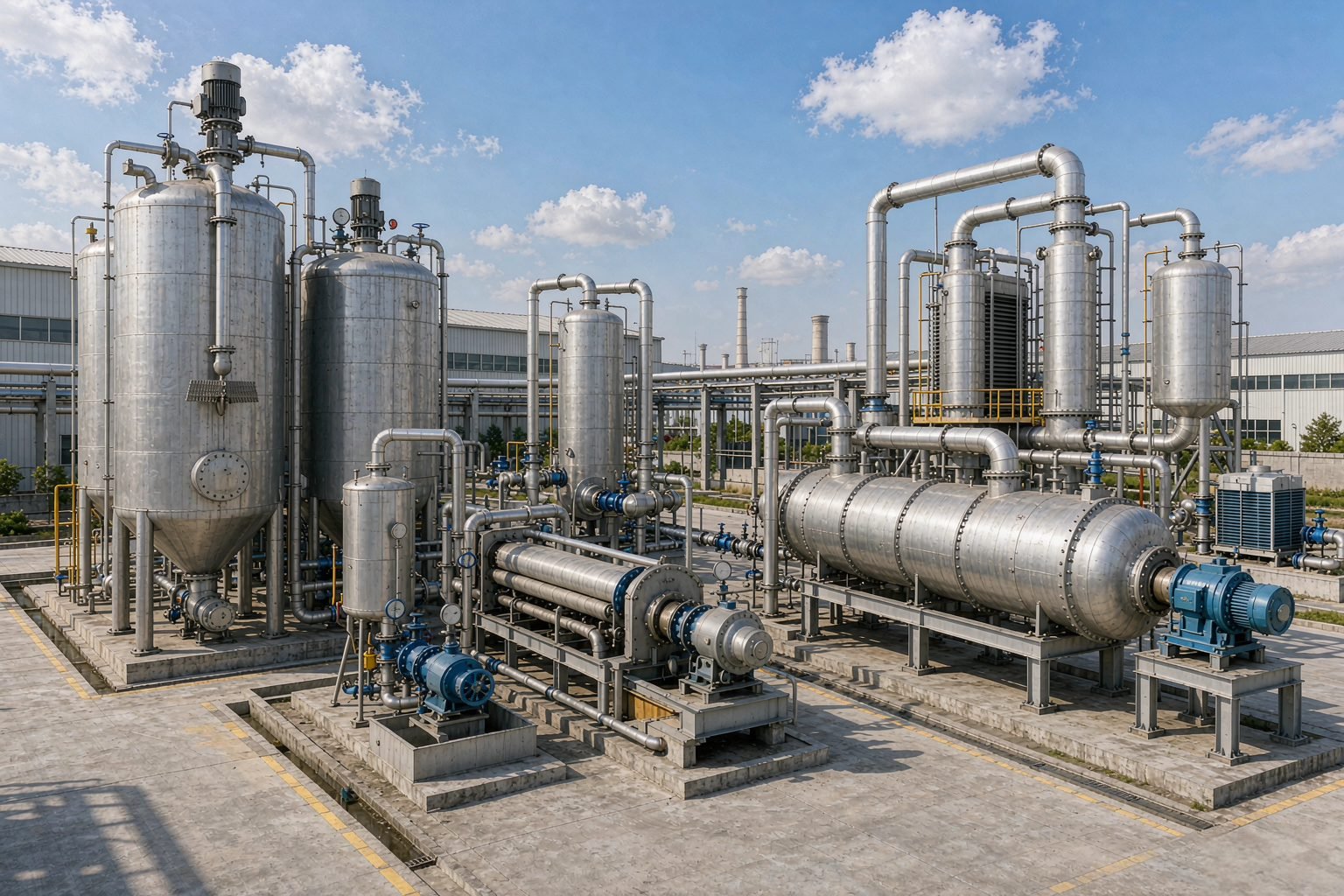
Tank bottom / refinery / drilling sludge
Set per project
Batch only
Recoverable oil, dry solid residue
What the plant processes
Sludge is the most variable feed we handle. The lists below are the starting filter — the actual design follows your lab analysis.
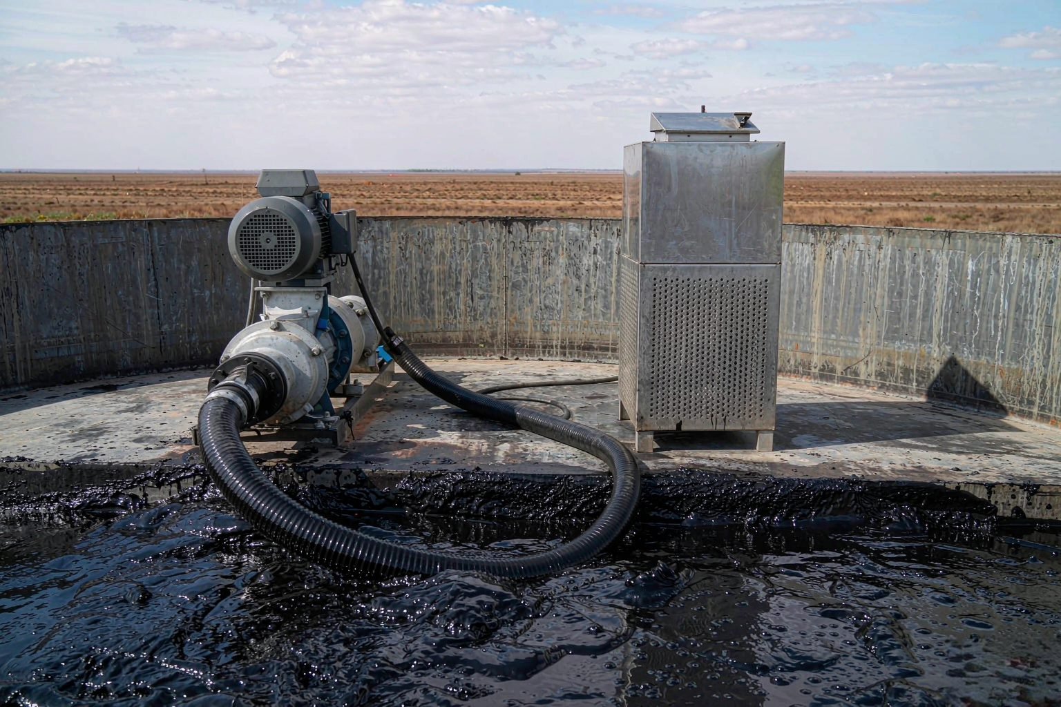
Typically suitable (after assessment)
- Tank bottom sludge from crude and product storage
- Refinery oily sludge from separation and desalting units
- Drilling mud and oily cuttings, after assessment
- Oily soil and separator sludge with moderate water content
- Blended sludge streams with known composition
Needs pre-treatment or assessment first
- Very high water content — dewatering or drying stage required
- Sludge with large solids, sand or debris — screening required
- Emulsified sludge that resists oil-water separation
- Mixed unknown hazardous wastes — composition must be characterised
- Sludge with high chlorine or acid content — case-by-case assessment
Batch operation — the only configuration we build for sludge
Sludge is charged, heated and discharged in cycles. Semi-continuous and continuous lines are not offered for sludge: the coke that forms on the reactor wall blocks a metered discharge, and the tyre-scraping method that keeps that wall clean only works inside a batch cycle.
Batch
Why we do not offer semi-continuous or continuous
- Coke builds on the reactor wall and blocks a metered discharge
- The tyre-scraping countermeasure only works in a batch charge
- Water and solids content swings between loads — each charge is trimmed
- Thick sludge will not meter at a set rate into a continuous line
From wet sludge to recoverable oil
Six stages. Pre-treatment and oil-water separation are the two stages that decide whether a sludge line performs as promised.
01
Reception & analysis
02
Pre-treatment
03
Charging
04
Heating & pyrolysis
05
Condensation & oil recovery
06
Solid discharge
Oil sludge cokes on the reactor wall — this is how we keep it moving
Oil sludge cokes as it heats. The coke hardens into a layer on the reactor wall, which slows heat transfer into the charge, shrinks the working volume and eventually forces a shutdown so the shell can be cleaned by hand.
On a sludge line that layer is the single biggest cause of unplanned downtime — so the design has to answer it, not ignore it.
- Heat transfer drops — longer cycles, more fuel per tonne
- Working volume shrinks — less feed per charge
- Manual cleaning means stopping the plant
Charge tyres with the sludge
The practical countermeasure is straightforward: charge a dozen to twenty scrap tyres into the reactor together with the sludge. As the charge moves, the bead wire and steel belt of the tyres rub against the reactor wall and scrape the coke layer off, so it leaves with the solid residue instead of hardening in place.
- A dozen to twenty tyres per charge, set to the reactor size
- Tyre bead and belt steel does the scraping
- Coke leaves with the residue instead of building up
- Fewer shutdowns for manual wall cleaning
The tyre count is set to your reactor size and sludge type and stated in the technical offer. It also means a sludge site needs a supply of scrap tyres — if you handle tyres as well, see our tyre pyrolysis line.
Optional configuration for a sludge line
Sludge is thick and sticky and does not flow like a liquid. Getting it into the reactor reliably is the first practical problem on any sludge project, which is why the screw feeder is the option most sludge sites take.
Screw (auger) feeding machine
A screw feeder forces conditioned sludge into the reactor instead of relying on it to flow or to be tipped in. It stops bridging and blocking at the inlet and keeps the charge rate steady — the standard choice for tank-bottom and refinery sludge.
What leaves a sludge line
Recoverable oil
Separated oil with caloric value, sold as industrial fuel or polished further in a distillation unit.
Dry solid residue
Volume reduced to a fraction of the wet feed; final disposal route is confirmed by testing against your local rules.
Process water
Separated water is collected for treatment before discharge or reuse on site.
Combustible gas
Non-condensable gas returns to the burner, cutting external fuel consumption.
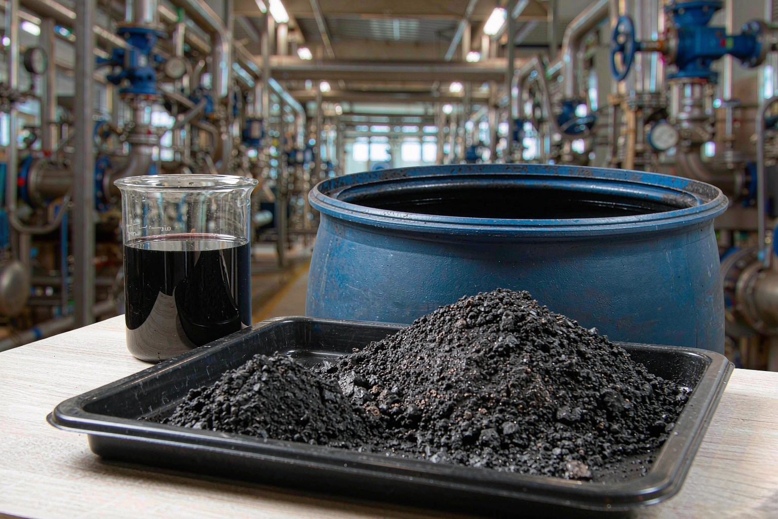
Specification sheet
Sludge projects are engineered, not catalogued — every value below is confirmed against your inlet analysis. The signed technical offer carries the numbers.
| Feedstock | Per inlet analysis: water, oil and solids content |
|---|---|
| Inlet limits | Stated per project after the sludge assessment |
| Pre-treatment | Screening / dewatering / drying, sized to the analysis |
| Feeding | Screw (auger) feeding machine available as an option |
| Coking control | Scrap tyres charged with the sludge; quantity set per reactor size |
| Operating mode | Batch, single reactor — no semi-continuous or continuous option |
| Heating method | External burner, fuel oil or gas fired |
| Cooling | Water-cooled condenser train |
| Oil recovery | Condensation plus oil-water separation |
| Solid discharge | Screw discharge with collection; residue testing per local rules |
| Emission control | Scrubber, flue treatment and odour control sized to local limits |
| Warranty | Per contract terms |
Send your sludge analysis
What surrounds the reactor decides how well the line runs
Sludge handling is unglamorous and decisive. Reception, dewatering, odour control and residue logistics are what separate a working sludge line from a demo unit.
- Sludge reception pit with mixing and transfer pumps
- Screening and dewatering or drying stage
- Screw (auger) feeder for metered charging (optional configuration)
- Water-cooled condenser train and oil-water separator
- Recoverable oil storage tanks
- Dry residue screw discharge and sealed collection
- Process water collection for treatment
- Flue gas scrubber, odour control and induced draft fan
- Control cabinet with temperature and pressure interlocks
Environmental scope
- Flue gas scrubbing before stack
- Odour control on sludge reception and tanks
- Wastewater collection and separation
- Dust control at discharge points
Permitting is a local process. We prepare the technical documentation your authority asks for; we do not issue permits or guarantee an approval.
Explore the related equipment
Four lines cover the waste-to-oil range. Open the one that matches your feedstock — each page carries the process, specification and enquiry form.
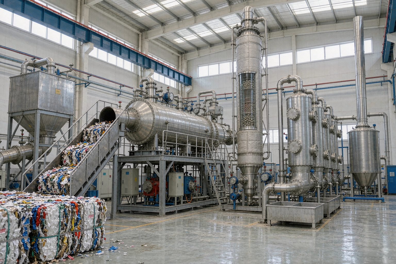
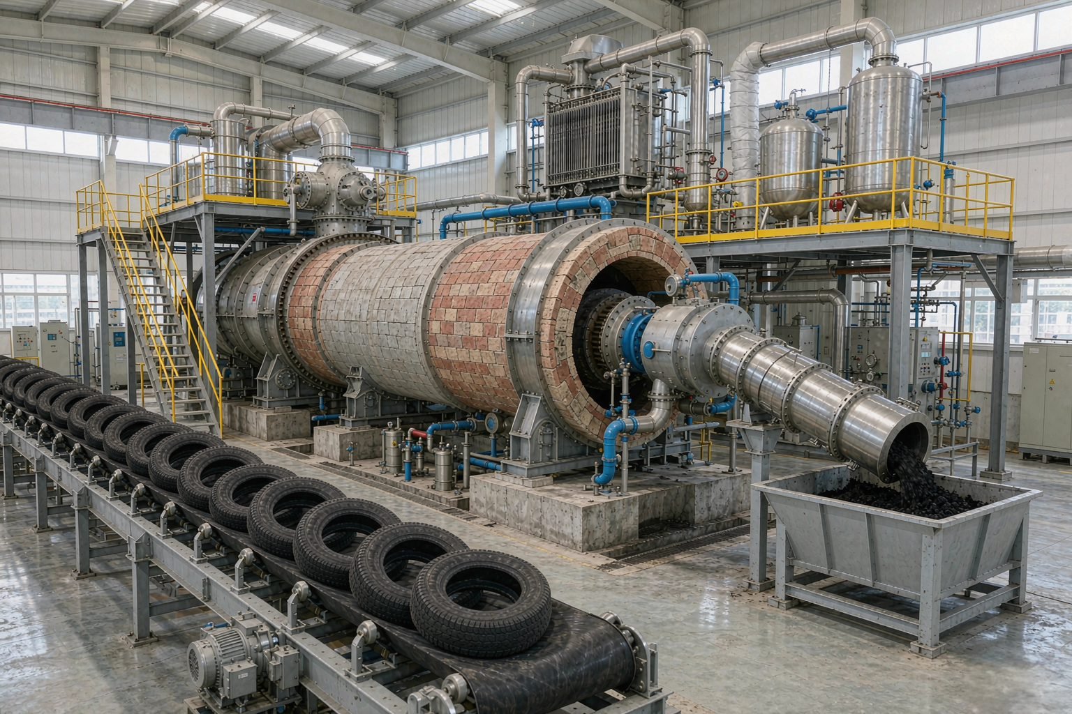
Tyre pyrolysis plant
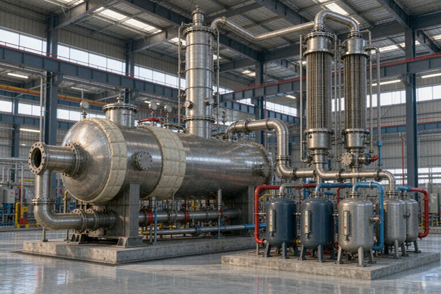
Waste oil distillation plant
A reference is only useful if it matches your feedstock
Tell us the sludge source and send the analysis. We will send the sludge projects that actually match — with configuration, commissioning date and the site you can contact — instead of a gallery of unrelated installations.
Before you order
A lab analysis or representative sample: water content, oil content, solids and any contaminants. Sludge varies more than any other feed — the analysis is the quote.
Then a dewatering or drying stage comes in front of the reactor. Pyrolysis is not a water treatment process — the pre-treatment sizing is a core part of the proposal.
The residue is dry and reduced in volume, but its final classification depends on the feed and your local rules. We design for residue testing and state the handling in the proposal; the disposal decision sits with you and your authority.
Recovered sludge oil is typically sold as industrial fuel or upgraded in our distillation unit. The realistic spec is stated after we assess the oil fraction of your sample.
Yes, it does — the coke hardens on the reactor wall, slows heat transfer and eventually forces a cleaning shutdown. We counter it by charging a dozen to twenty scrap tyres with the sludge: the tyre bead and belt steel scrapes the coke off the wall so it leaves with the residue. The tyre count is set to your reactor size and stated in the offer.
No. We build sludge plants as batch units only. The coke layer on the reactor wall, the swing in water and solids between loads and the behaviour of thick sludge at an inlet all work against a metered continuous feed — a continuous line would spend its time blocked or shut down for cleaning. The batch reactor is the dependable configuration, and the screw feeder only makes charging faster.
Most sludge sites take it. Sludge does not flow like oil, so a hopper alone tends to bridge and block at the inlet. The screw feeder forces the conditioned sludge in at a steady rate — we size it from your water and solids content.
No. Pyrolysis changes how you treat the waste; the permit regime is local and stays your responsibility. We supply the technical documentation your authority asks for.
Still deciding?
Send the sludge analysis and the tonnage
A lab report with water, oil and solids content plus your target tonnage is enough for us to size the line and quote.
- Inlet analysis review
- Pre-treatment design
- Layout and delivery terms